[ String Reader ]

Where the String Becomes Data.

Listens to every module on the string simultaneously — decoding PLC signals, measuring string voltage and current at 16 Hz, and feeding the raw intelligence that powers everything upstream.

DC in · PLC from 40 modulesRS485 → Gateway
SUNSNIFFER · STRING READER
16 Hz · ACTIVE8.42 A
40/40 modules · PLC lock
PWRPLCBUS
IP20 · field-mountedV + A · 16× per second
the whole string · read simultaneously
01
What It Does

One Job: Pick Up What Every Module Is Saying.

Every module sensor transmits its data over the existing DC cable. The String Reader listens.

Module sensors send voltage and temperature as PLC signals — over the string cable that is already there. No data wiring, no extra network.

The String Reader picks up this PLC data from the string, decodes it, and forwards it to the Gateway. That is the core job — and both members of the family do it.

A
String Reader — wired in
Picks up the PLC data and additionally measures string voltage and current itself — 16× per second.
B
X-String Reader — clamped on ADD-ON
Add-on member of the family: picks up the same PLC data through the String Claw — clipped around the cable, nothing opened. String current comes from the inverter.
02
The Family

One Family. One Real Decision: In-Line or Clamp-On.

Every version delivers module-level data. The difference is how it connects to the string — wired in for full measurement depth, or clipped on for effortless retrofit.

PATH A · IN-LINEwired into the string — measures everything itself
String Reader — full 16 Hz measurement

The classic instrument: string voltage and current at 16 Hz plus module-level PLC data. Two variants, same measurement capability:

STANDARD
String Reader

The full measurement instrument. Everything the platform needs for DiodeVital, TrueSTC and IEA classification.

NEC 690.12
RSD
String Reader — RSD

Same measurement — plus a built-in rapid-shutdown signal generator. On shutdown, modules drop to safe 1V mode.

IN DEVELOPMENT
PATH B · CLAMP-ON · IN DEVELOPMENT
X-String Reader + String Claw

Nothing is opened or disconnected. The String Claw clips around the string cable, picks up the module data, and plugs into the X-String Reader via USB.

With one MPP tracker per string, the string current comes from the inverter and is merged in the Gateway. Where strings share a tracker, the X-String Reader adds its own current measurement.

01 clamp02 plug03 connect — done
See how it works
At a glance
String Reader
String Reader — RSD
X-String Reader
Installation
String ReaderWired into the string
String Reader — RSDWired into the string
X-String ReaderClipped around the cable
Module data (V + T)
String Reader
String Reader — RSD
X-String Reader
String V + I at 16 Hz
String Reader
String Reader — RSD
X-String Reader— (current from inverter)
Rapid shutdown (RSD)
String Reader
String Reader — RSD✓ built-in
X-String Reader
Best for
String ReaderFull measurement depth
String Reader — RSDPlants requiring NEC 690.12
X-String ReaderFast, non-invasive retrofit
03
What It Measures

String Voltage. String Current. Every Module.

Three data streams. One device.

Architecture · string → cloudLive
modules · sensor on eachV + T · every 15 sPLC over DCSTRING READER16 HzV · I · PLC decodeRS485 / Modbus RTUGATEWAYAggregatecloud · analytics1 String Reader = up to 40 modules1 Gateway channel = 30 String Readersmodule telemetry · 15 sstring electrical · 16× per secondstructured · cloud-ready
0116 Hz
String Voltage
Measured continuously at 16 Hz across the full string.
0216 Hz
String Current
Detects fast electrical events including arcing and inverter switching.
0315 s
Module-Level Data
V and T from every SunSniffer sensor on the string via PLC, every 15 s per module.
04
DSP Option

Central Inverter Noise? There's a Slot for That.

Every String Reader ships with a built-in DSP expansion slot — ready before you ever need it.

Signal path · central inverter environmentDSP active
DC LINE · RAW PLC + INVERTER NOISEDECODED PLC · AFTER DSP FILTERINVERTERDSPSIGNALFILTERINGCLEAN

Central inverters switch a lot of power in one place — and that generates significant electrical noise on the shared DC line. In these installations, the PLC signal carrying module-level data can get buried in that noise.

The optional DSP board plugs directly into the dedicated slot inside every String Reader. No tools, no rewiring. It applies advanced signal filtering that pulls the PLC signal cleanly out of a noisy central-inverter environment.

The slot ships in every unit, standard or RSD. Add the board only where the site needs it — no different hardware to stock or spec in advance.

05
Installation

Two Paths In. One Cable Out.

In-line versions wire into the string. The clamp-on X simply clips around it. Either way, everything ends in a single RS485 run to the Gateway.

PATH A · IN-LINEString Reader · RSD
Wired into the string — by a qualified PV electrician.
01DC string access before the inverter
02RS485 daisy-chain between String Readers
03Single RS485 run from chain to Gateway
WHY WIRE IN

The in-line instrument measures string voltage and current itself, at 16 Hz — capturing arcing signatures, fast transients and switching events directly in the device, independent of any inverter.

PATH B · CLAMP-ON · IN DEVELOPMENTX-String Reader + String Claw
Clipped around the cable — in minutes, no DC work.
01Clip the String Claw around the string cable next to the inverter
02Plug the USB connector into the X-String Reader
03Single RS485 run to Gateway — done
NOTHING OPENED · NOTHING STOPPED

Strings stay connected, the plant keeps producing. String current comes from the inverter and is merged in the Gateway. Details below ↓

BOTH PATHS END THE SAME WAY — RS485 DAISY CHAIN · ONE CABLE TO THE GATEWAY
RS485 daisy chain · one bus1 cable out
SR01SR02SR03SR04up to 30SR30GATEWAY1 channel · 30 readers · 1,200 modules
DC in · before the inverterRS485 → Gateway · Modbus RTU
06
X-String Reader + String Claw · In Development

No Cable Opened. No String Disconnected.

The clamp-on alternative to the classic String Reader — module-level data from any string in minutes. Currently in development; availability on request. Where several strings share one MPP tracker, it adds the string-current measurement the inverter cannot provide.
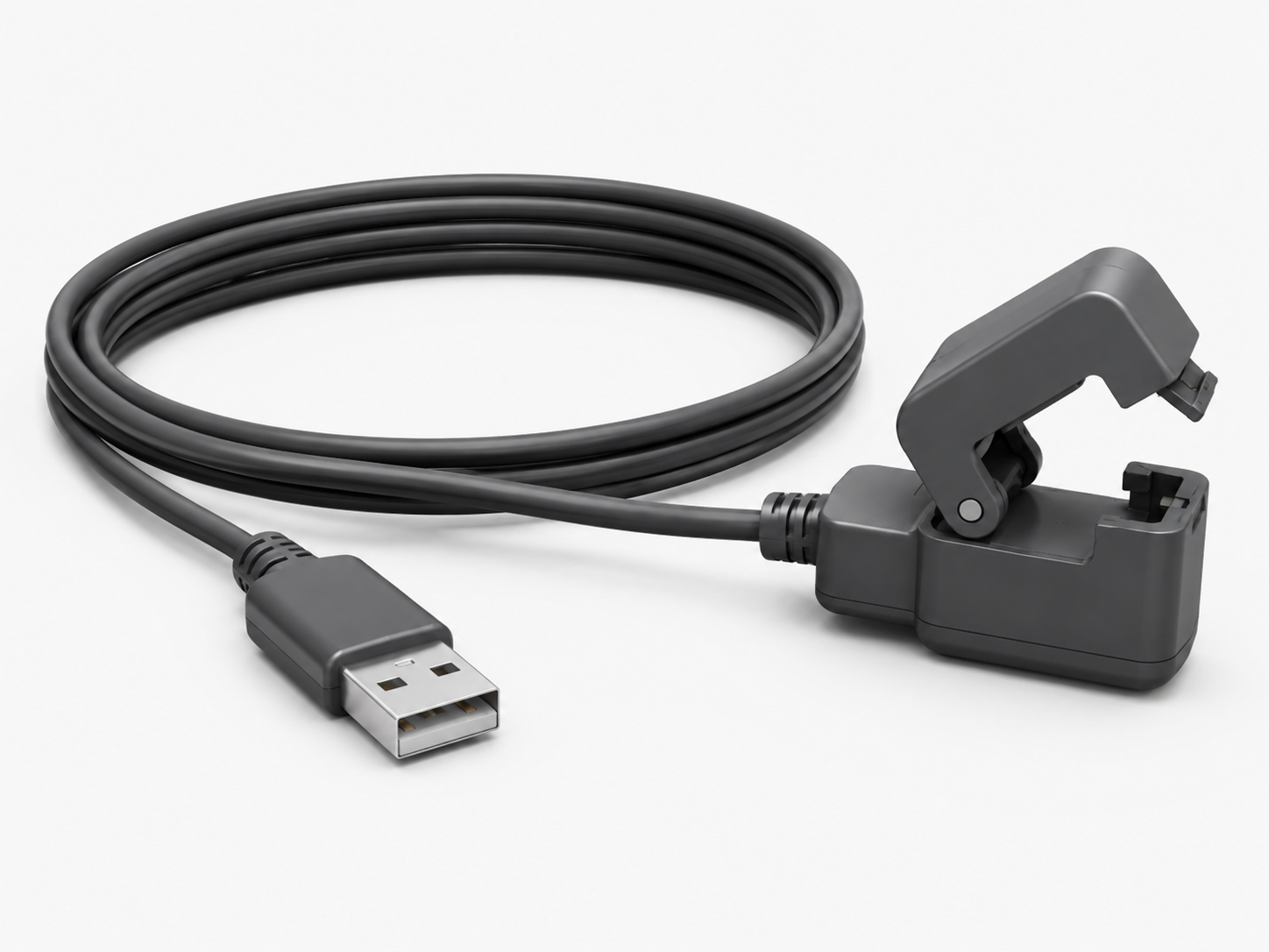
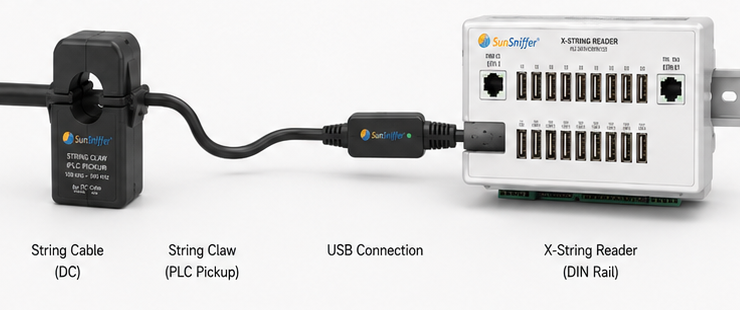
String Claw — clamp-on PLC pickup with USB interface
String Claw · clamp-on PLC pickupUSB · 1.5 / 3 / 5 m
String Claw clamped on the DC string cable, connected by USB to the X-String Reader on a DIN rail
X-String Reader · 16 USB ports · DIN railRS485 → Gateway
INSTALLATION · THREE STEPS
01
Clamp
Clip the String Claw around the string cable next to the inverter. No cable opened, no string disconnected, no downtime.
02
Plug
Plug the USB connector into any of the 16 ports on the X-String Reader. Power and data over one cable.
03
Connect
Connect the X-String Reader to the Gateway via RS485. Done — module-level data is flowing.
WHAT IT MEASURES — AND WHAT IT DOESN'T

The String Claw reads module-level data transmitted over the PV cable — module voltage and module temperature — without touching the DC connection. String current is not measured by the claw: it is taken from the inverter and combined with the module data in the Gateway.

16 × USB portsPLC 100–500 kHzcable Ø 10–12 mm0–20 A DCDIN rail · 35 mmRS485 out
07
Specifications

The Numbers — For the Whole Family.

IN-LINE · STANDARD
String Reader
String voltage
up to 1500 V
String current
up to 20 A
Sampling rate
16 Hz
Measurement class
Class 1
Module sensors / string
up to 40
Readers / Gateway ch.
up to 30
Communication (out)
RS485 / Modbus RTU
Enclosure
IP20, separate mount
Firmware updates
Remote, over the air
DSP expansion
Built-in slot, optional board
NEC 690.12
IN-LINE · RSD
String Reader — RSD

Additional functions — on top of all String Reader specs listed left:

RSD signal generator
Integrated PLC keep-alive
Shutdown behaviour
Modules drop to safe 1V mode
Separate RSD transmitter
Not required
Compliance
NEC 690.12 rapid shutdown
Measurement capability
Identical to Standard
IN DEVELOPMENT
CLAMP-ON · X
X-String Reader + String Claw

Add-on to the String Reader family — clamp-on connection instead of in-line wiring:

String Claw inputs
16 × USB 2.0 ports
PLC signal detection
100 – 500 kHz
Module data
V + T via PLC — no cable opened
String current
From inverter, merged in Gateway
Clamp fits cable
Ø 10–12 mm (6 & 10 mm² PV)
DC current on cable
0 – 20 A
Claw cable length
1.5 / 3 / 5 m
Communication (out)
RS485, daisy-chainable
Mounting
DIN rail 35 mm · 240×110×65 mm

Ready to See What Your Strings Are Really Doing?

Part of a complete measurement architecture — sensor, String Reader, Gateway, analytics.

Download Datasheet Book a Technical Discussion